
The manifold should control pressures by using one of several chokes. Some of the conditions that the manifold may be called upon to work under are a variety of fluids such as mud, oil, water, or gas, high pressures, upstream flow rates, downstream velocities, and obstructions in the produced fluids such as sand, shale, 01 pipe protector rubbers. The choke manifold is an arrangement of valves, lines, and chokes designed to control the flow of mud and kick fluids from the annulus during the killing process. The preventer may be a low-pressure sphcrical preventer or some type of diverter bag used to direct the flow into the lines.Ĭhoke Manifold. Angles and bends should be minimized in the diveiter lines to avoid unnecessary restrictions. The lines should be as large as possible with a suggested minimum ID of 6 in. 16-68 Typical diverter stack (Courtesy PennWell Publishing) Examples describing how one can use the model to better design well tests i n commingled formations are also included.Close bag ''Open valves Open bag ^' Close valves fnr" " - Preventer valveįig.

The degree to which crossflow affects pressure response can also be measured. This feature enables the engineer to simulate the actual flow rate coming from each layer and the resultant reservoir response as measured downhole from a pressure recording tool. Reservoir and wellbore equations are solved simultaneously using the fully implicit Newton method.Īpplications for this model include determining the dynamic wellbore pressure drop versus time for both single phase oil or gas, and multiphase production and shut-in in vertical and deviated wells, and the resultant change in production rates at the wellbore sandface with time.
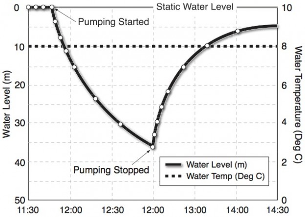
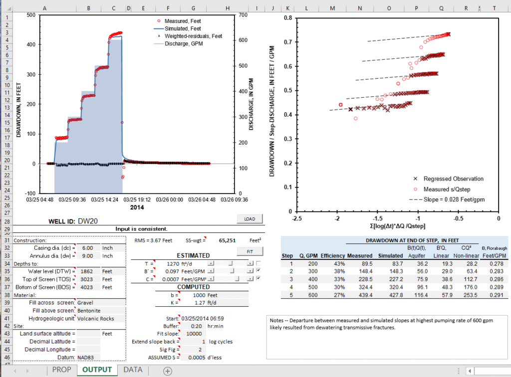
#WELL DRAWDOWN TEST EASTERN WASHINGTON SKIN#
The wellbore flow is handled by use of the Bernoulli equation including friction and kinetic contributions to pressure drop.Īnother feature of this model is the use of the full rate equation for gas flow in the reservoir, including the inertial-turbulent (forcheimer) term, in order to handle the rate-dependent skin in addition to mechanical skin at the wells.

This coupling allows the user to assign production, injection, and shut-in of wells at the surface point, where the valves are physically located, instead of downhole for conventional reservoir simulators. This paper describes new applications of a recently developed integrated single well model (ISWM) that couples equations describing dynamic wellbore flow with ones describing transient reservoir flow. A complicating factor comes in if the layers are communicating, which may significantly reduce the accuracy of available analytical methods. depth in addition to downhole pressure is required so as to ascertain how much rate is coming from each layer in order to analyze the response of each layer separately. Often, measurements of both downhole rates vs. The problem of designing and analyzing well tests for wells producing from multiple zones through the same production string is often complicated by the interaction between the different layers.


 0 kommentar(er)
